Home > Ocean Liners > QE2 > QE2's 1987 Rebuild
QE2's Major 1986 - 1987 re-engining refit
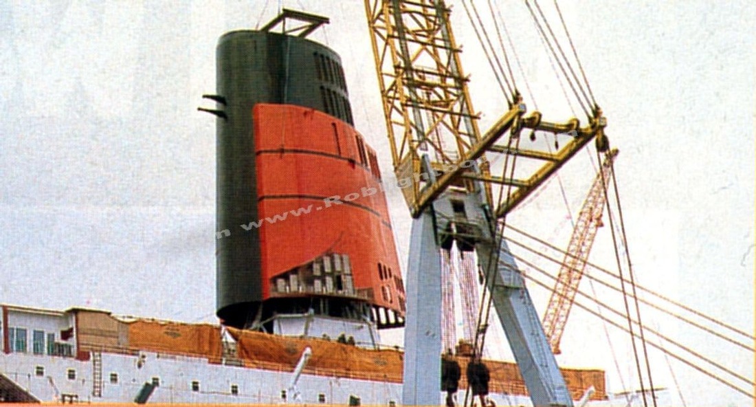 QE2's new, fatter funnel is fitted during the final stages of her conversion
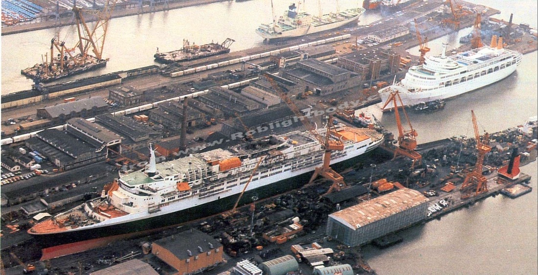
From October 1986 to May 1987, QE2 underwent a major refit at the Lloyd Werft yard at Bremerhaven in Germany transforming her from an ageing steamship to a state of the art diesel-electric motorship. This refit, costing $162m, was hugely successful and allowed the ship to sail on for another 20 years as the Cunard flagship, the only transatlantic liner and the fastest and most powerful merchant ship in the world.
This refit is of particular interest to me because I was onboard as she left the yard to go on her trials and because my Dad had worked with QE2 up until this point.
QE2 became the longest serving Cunarder of all time, travelled further than any ship ever and was in service for nearly 40 years (May 1969 until November 2008). This would not have happened without this refit.
A massive gamble that paid off : The biggest ship conversion ever for the fastest passenger liner afloat with the most powerful diesel installation afloat and the largest electrical propulsion motors ever built.
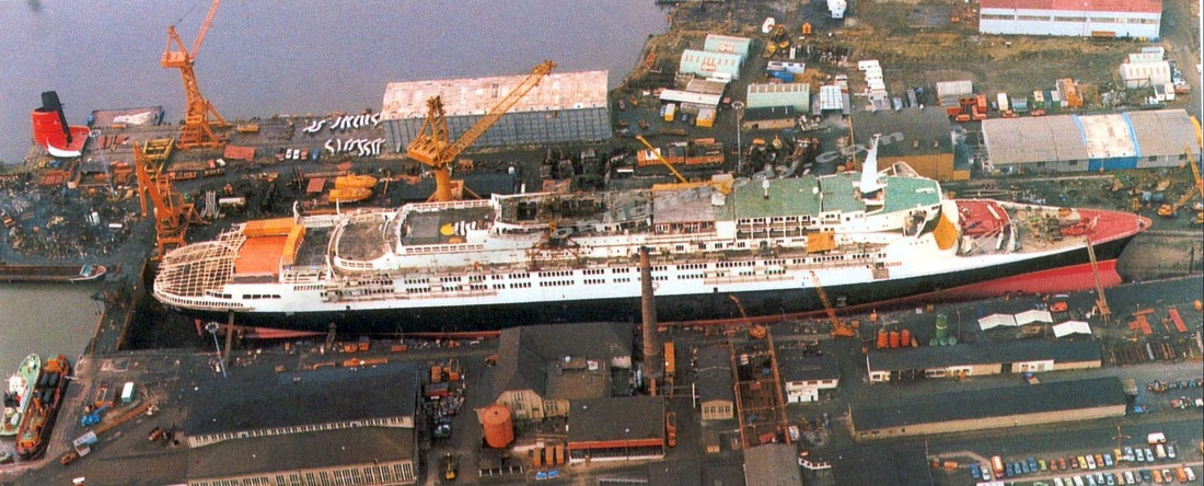
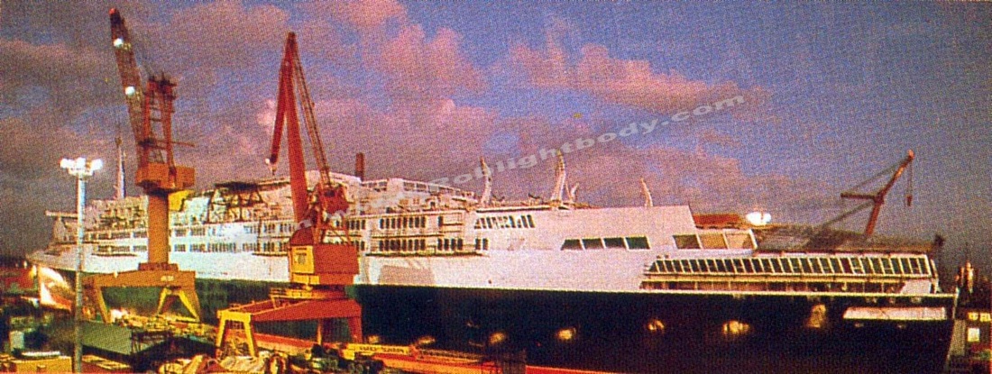
QE2 goes topless during her "heart transplant".
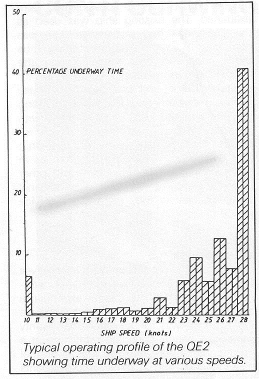 QE2's time spent operating at various speeds.
Feasibility Study & options
Initial indications of fuel savings of 30% annually on the ships current 12,000 tons consumption provided the impetus to studying further the feasibility of re-engining. Fuel costs at the time were $185 per ton, meaning a potential saving of $6.5 million per year.
Engine manufacturers and shipyards worldwide were requested to make re-engining proposals while Cunard considered their options, including doing nothing for the remainder of the ships life. QE2's transatlantic service speed of 28.5 knots would require the installation of an extremely high total horsepower while also requiring the flexibility for cruising, manoeuvring and in-port modes.
- The Maxi-Boiler alternative was to cost 1.89 more than the baseline cost (of doing nothing) and would result in a significant improvement in performance of the existing steam plant. 2 diesel alternators would replace the turbo alternators in order to reduce fuel consumption in the generation of electricity and to reduce the load on the boilers.
- The Maxi-Alternator alternative would have 2 instead of 3 diesel alternators which meant greater maintenance and availability but increased maintenance cost.
- The Diesel Conversion option would require the greatest initial cost of 3.42 times the baseline cost, and the greatest out of service time, but would result in the greatest operating cost savings from the highly fuel efficient diesel engines, new controllable pitch propellers and waste heat systems, propulsion plant automation, a full maintenance agreement and automating monitoring systems meaning increased equipment availability.
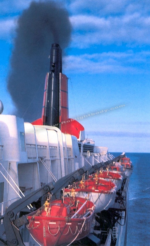 QE2 races up-channel at 30 knots on one of her final turbine-driven crossings
The Final Choice
The economical benefits of re-engining QE2 were even greater than originally thought, even considering the $53 million budget for the conversion, the 5 to 8 months out of service and the 12 to 14 months lead time for the implementation, the potential commercial benefits justified embarking upon phase II of the study. Re-engining would increase profit, life cycle cash flow, reliability, maintain a prestigious image and was cheaper than building a new ship.
Three diesel power plant designs were considered
It was expected that payback could be obtained in under four years.
The economical benefits of re-engining QE2 were even greater than originally thought, even considering the $53 million budget for the conversion, the 5 to 8 months out of service and the 12 to 14 months lead time for the implementation, the potential commercial benefits justified embarking upon phase II of the study. Re-engining would increase profit, life cycle cash flow, reliability, maintain a prestigious image and was cheaper than building a new ship.
Three diesel power plant designs were considered
- Diesel engines with main reduction gears with both (a) constant and (b) variable speed propeller shaft
- Diesel-electric propulsion (having no main reduction gears)
It was expected that payback could be obtained in under four years.
The Specification for the bidders
- Conversion of QE2 to keep her in service for at least 20 more years* (*21 years later, her powerplant had plenty of life left)
- Higher standard of passenger facilities
- Significantly reduced operating costs.
- 28.5 knots to be produced with only 85% of all power.
- Noise & Vibration levels in passenger spaces not to increase
- Plant should be fully automated and designed for unmanned engine room
- Conversion should take no more than 7 months
Planning
Initial planning was vital in order for the total timescale not to be exceeded. Layout of machinery, calculations of stability, longitudinal stresses were all crucial. A computer program was developed to provide a detailed production/time schedule for the complete project. During the work, progress was constantly checked against the computer programme and mostly went to plan.
A model was created of the entire complete machinery installation built to 1:20 scale in a number of removable sections and was used for taking measurements of all piping systems. The model was essential for the design and installation of the whole machinery.
The crucial model of the
completed machinery installation
Arrival & clearout
Immediately after the ship docked, transport openings were made in the vessel as prerequisite to the conversion work and the famous funnel was dismantled. The funnel's opening was then used as a winding shaft for the removal of 4,700 tons of old machine parts and for access for the new installation weighing in at around 4,500 tons.
Immediately after the ship docked, transport openings were made in the vessel as prerequisite to the conversion work and the famous funnel was dismantled. The funnel's opening was then used as a winding shaft for the removal of 4,700 tons of old machine parts and for access for the new installation weighing in at around 4,500 tons.
A floating crane was brought from an oil platform on the North Sea to lift the heavy and bulky scrap from the vessel's interior. The dismantling also included the removal of 2 propeller shafts consisting of 6 segments of 600mm in diameter and over 10m long. Each part weighed around 25 tons. All work below the waterline was completed on schedule by the 3rd of December and included the new 80 ton, 16.5m long shafts in place.
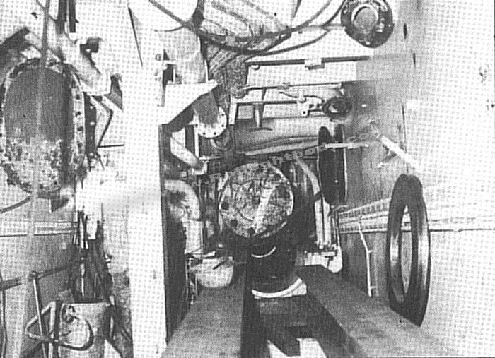
Work inside the cramped shaft tunnel
|
The new tailshaft being fed into the stern boss
|
Everything between frames 118 and 164 was completely stripped out, with much cutting up of equipment in place to facilitate handling. An empty shell was created in the hull before the new machinery installation began.
At the same time as the stripping out of the machinery, the hull was gritblasted and two new propellor shafts, supplied by Lips BV with two new controllable pitch highly skewed propellors and Grim Wheels were fitted.
At the same time as the stripping out of the machinery, the hull was gritblasted and two new propellor shafts, supplied by Lips BV with two new controllable pitch highly skewed propellors and Grim Wheels were fitted.
The End of the Turbines and the boilers
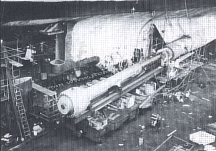
After 19 years (of not completely reliable service) of developing 55,000 shp each at 174 rpm, which took the ship a record breaking 2,622,858 miles, the John Brown steam turbines had been powered down for the final time. They were the penultimate Pamatrada turbines to be built. The three Foster Wheeler boilers were also shutdown for the last time.
Here the turbines are shown in the John Brown factory at Clydebank being tested and as a massive pile of scrap at Bremerhaven. Removing these and all the auxiliary machinery and pipework was in itself a mammoth task taking some 6 weeks and involved the removal of 5,000 tons of metal and equipment.
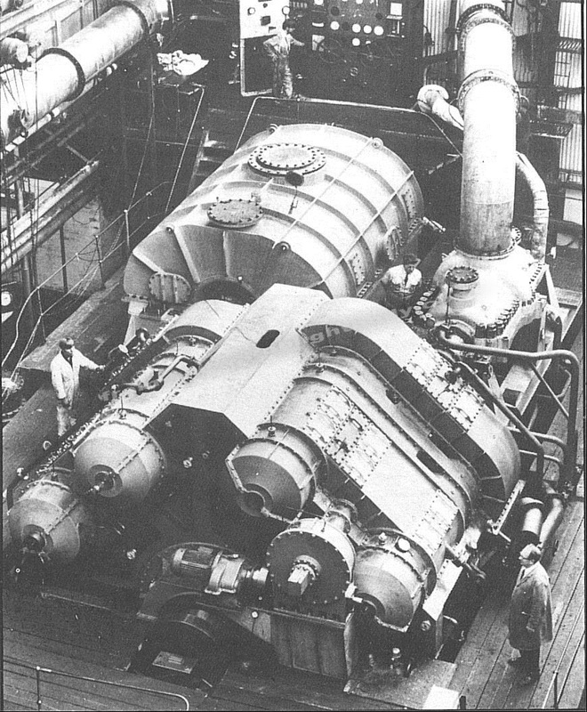
The original steam turbines prior to original installation in 1967.
|

The original engines scrapped in 1986
|
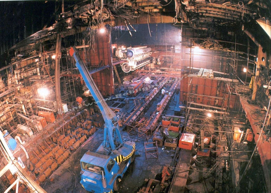
The emptied engine room
|
QE2 becomes State of the art once more.
The engine room tank tops and new foundations for the nine M.A.N. B&W 9L58/64 medium speed engines and generators and the two new GEC propulsion motors, were prepared by first removing the double bottom in way of the machinery space, creating new double bottom tanks and the new seatings. The new engine foundations were lowered through the funnel shaft by the mammoth HEBE2 floating crane which can lift up to 350 tons - the weight of each motor.
This work was carried out at the same time as the dismantling of the old plant. The nine engine foundations were lowered in a vertical position then tilted horizontally and lowered onto skids to be moved to their final position. Each bed weighed 50 tons was 17m long and 3m wide. The foundations were placed immediately the burning out had been completed - i.e. when lowered through the funnel hatch, there was still nowhere for them to go, the schedule was incredibly tight.
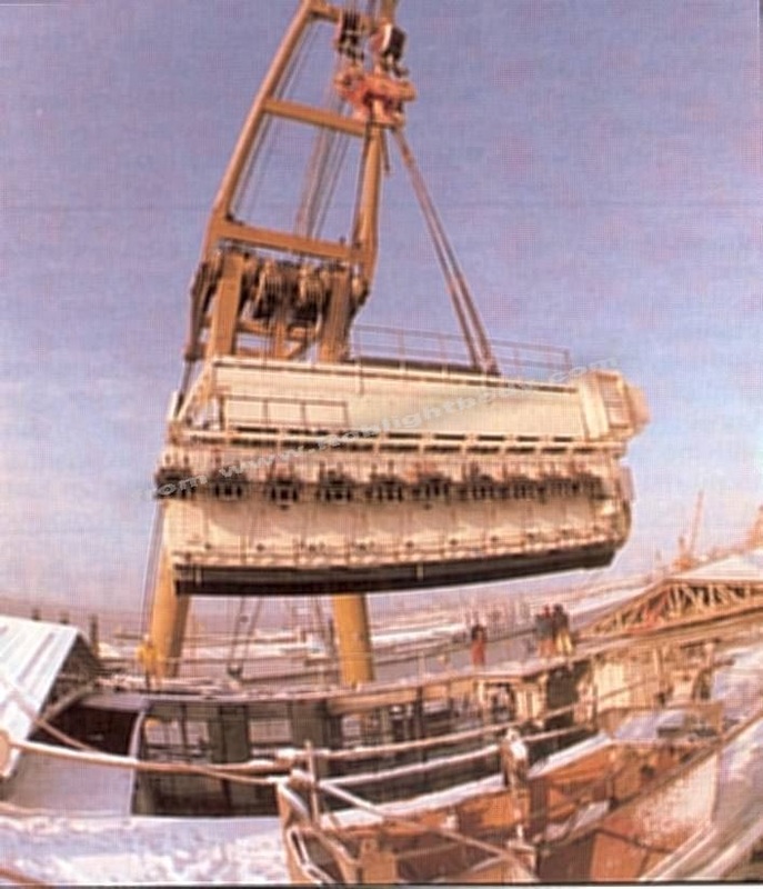
After installation of the foundations, the two 450 ton electric propulsion motors were lowered through the funnel hatch, moved on skids and installed onto their foundations (taking one full day each to accomplish). Next, the nine 220 ton diesel engines were lifted in and moved on skids to their foundations.
The engine room tank tops and new foundations for the nine M.A.N. B&W 9L58/64 medium speed engines and generators and the two new GEC propulsion motors, were prepared by first removing the double bottom in way of the machinery space, creating new double bottom tanks and the new seatings. The new engine foundations were lowered through the funnel shaft by the mammoth HEBE2 floating crane which can lift up to 350 tons - the weight of each motor.
This work was carried out at the same time as the dismantling of the old plant. The nine engine foundations were lowered in a vertical position then tilted horizontally and lowered onto skids to be moved to their final position. Each bed weighed 50 tons was 17m long and 3m wide. The foundations were placed immediately the burning out had been completed - i.e. when lowered through the funnel hatch, there was still nowhere for them to go, the schedule was incredibly tight.
After installation of the foundations, the two 450 ton electric propulsion motors were lowered through the funnel hatch, moved on skids and installed onto their foundations (taking one full day each to accomplish). Next, the nine 220 ton diesel engines were lifted in and moved on skids to their foundations.
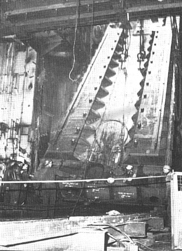
One of the engine bedplates being lowered into the machinery space
|
A complete engine being lowered
|
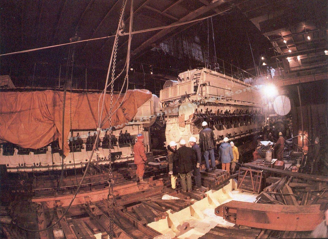
Main engines being manoeuvred on skids
|
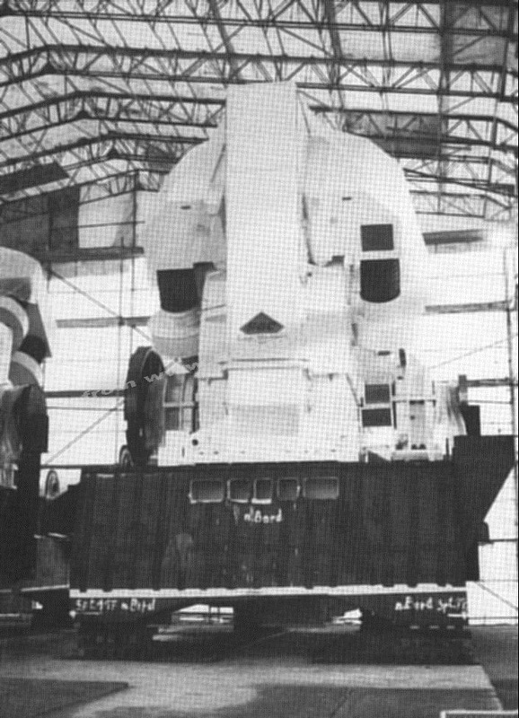
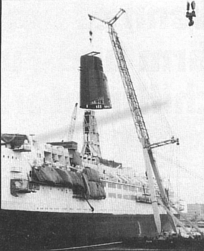
One of the giant GEC propulsion electric motors before installation and being lowered through the funnel hatch. The funnel can be seen on the quayside off to the left. The ships mast is to the right.
|
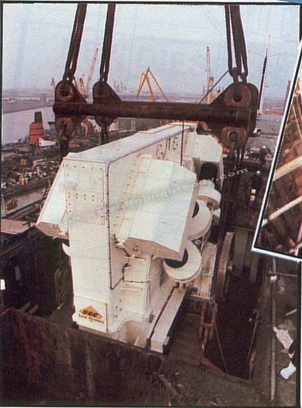
One of the giant GEC propulsion electric motors before installation and being lowered through the funnel hatch. The funnel can be seen on the quayside off to the left. The ships mast is to the right.
|
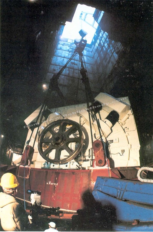
One of the 2 electric motors coming to rest on the engine room floor
|
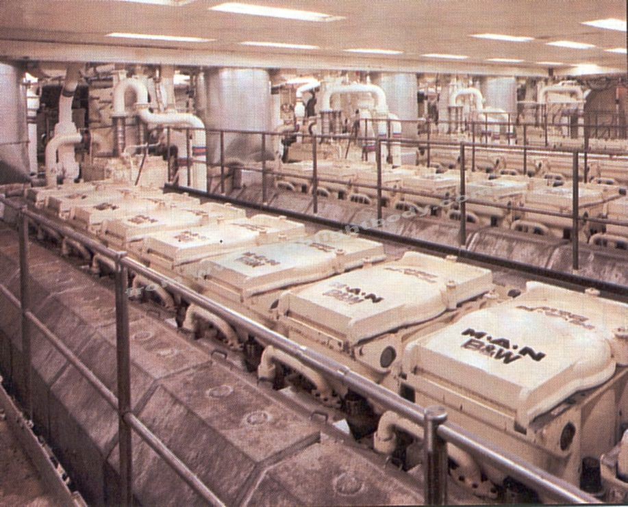
Views across the cylinder tops of four of the 9 main engines
|
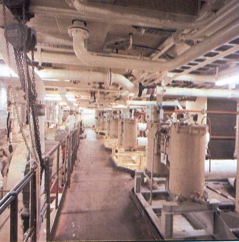
Lubricating oil filters and water coolers
|
|
Each 9L58/64 engine is rated at 10,620 kw (14,445 bhp) at 400 rev/min. Each engine is directly resiliently mounted onto the ships foundation and flexibly coupled via Vulkan Ratio couplings to two-bearing, totally enclosed, water cooled, salient pole, three-phase, synchronous GEC alternators of 10.5MW, 10kv, 60 cycles. Each alternator is rigidly mounted on the ship's foundation.
The power generated is supplied to a common 10 kV busbar system divided into two separate GEC/Field & Grant main switchboards, installed in two separate compartments, each of the main switchboards is again subdivided in two bus sections allowing a variety of operating modes.
This common busbar supplies power at 10kV directly to the two GEC Large Machines 44MW, 60 cycle synchronous motors, running at 144 rev/min (the largest propulsion motors ever supplied for marine use).
Electric power to all ship and domestic consumers is also supplied from the common busbar via two GEC liquid cooled 10kV/3.3kV transformers of 11 MVA capacity each. By this arrangement, a redundancy of 100 per unit is given for ship load.
To allow the ship to operate at high efficiency even at low ship speed and during manoeuvring, the normal constant propeller speed of 144 rev/min can be reduced down to 72 rev/min. This is achieved by two GEC synchro drives (thyristor convertors) of 11 MW each. These converters will be used for soft starting and speeding up the synchronous motors.
The driving power of the synchronous motors is transmitted via a new twin shaft arrangement to two new five-bladed c.p. propellers of 5.8 meter diameter each. At cruising speed, the variable-pitch propellers operate at 144 rev/min. Adjustment to the ship's speed is by varying the pitch of the propeller blades.
A further improvement of the efficiency of the c.p. propellers is achieved by a Grim vane wheel downstream of each propeller. The function of this vane wheel is given by the special shape of the blades which operates as a turbine in the inner part and as a propeller in the outer part. Each vane wheel is seven bladed and has a diameter of 6.7 metres and therefore the largest-ever built and implemented in a twin screw vessel. This new shafting c.p. propellers and vane wheels including their sophisticated controlling equipment have been supplied by Lips.
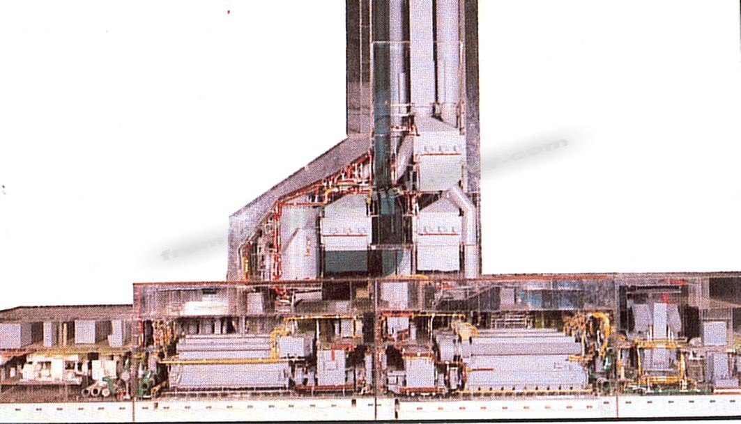
Plans of the new Diesel-Electric Machinery Arrangement on QE2
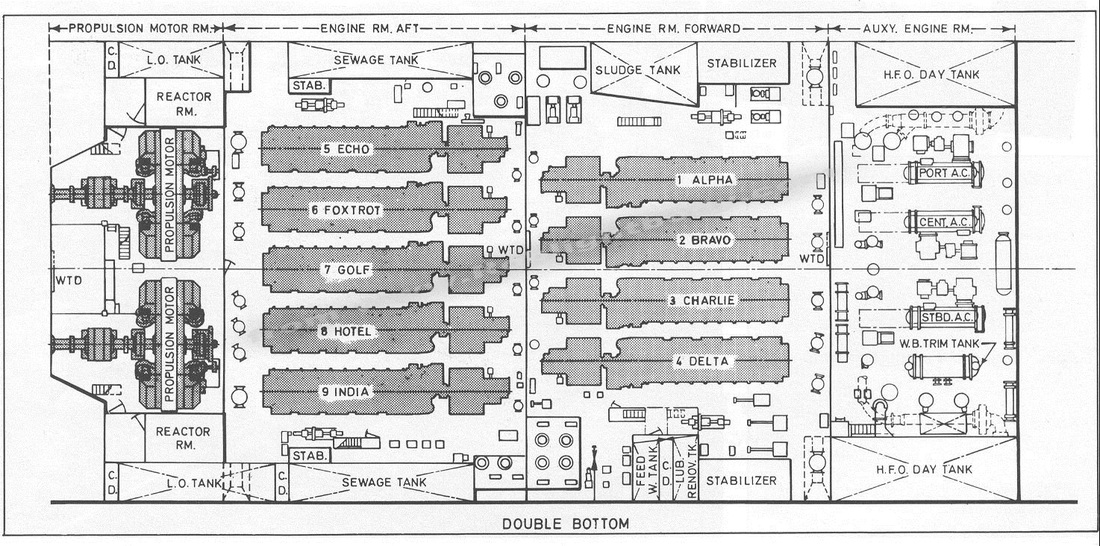
Plan of the Double Bottom showing the 9 engines and 2 motors.
|
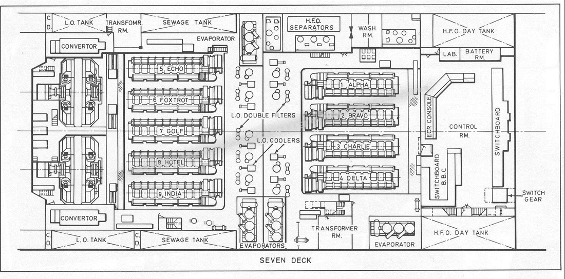
Plan of Seven Deck including the control room
|
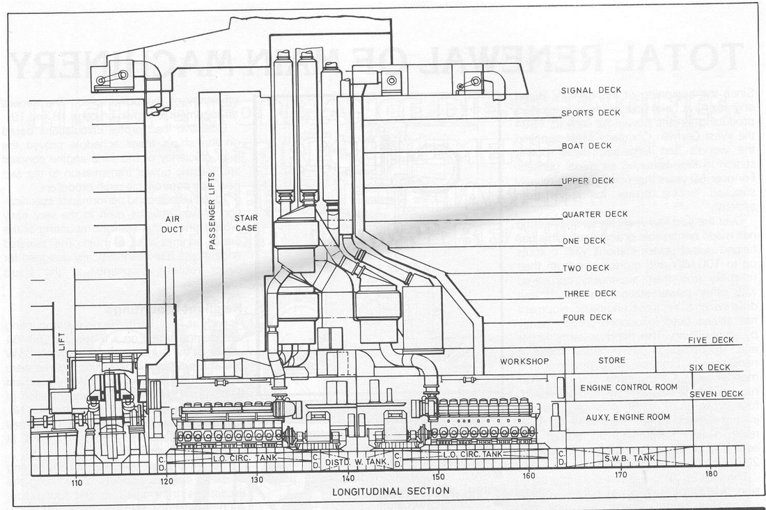
Longitudinal Section showing all the way down from the signal deck to the double bottom
|
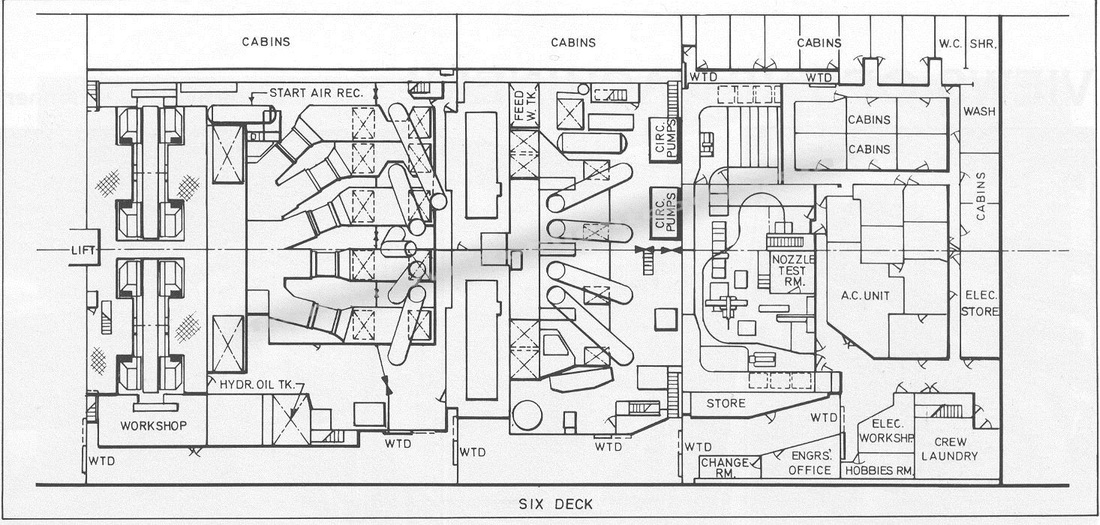
Plan of six deck
|
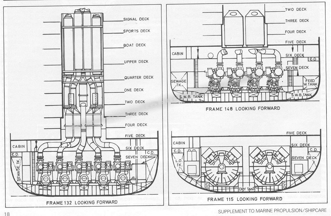
QE2 Cross Section view looking forward
All the new machinery is installed in four separate compartments. The general arrangement drawing shows the two compartments for four and five diesel-generator sets respectively.
The propulsion motors have their own compartment aft of the engine rooms, whilst certain auxiliary systems are situated forward of the two engine rooms. Due to direct resilient mounting of the diesel engines, resulting in low installation height, additional space in the form of 6th and 7th deck in the area of machinery space was created for installing most of the auxiliary equipment. For the operation of this power plant optimised auxiliary systems are installed.
One of the most attractive features of the new propulsion system is its high cost effectiveness. This is achieved partly by the low specific fuel consumption of the diesel engines and partly by the recovery of waste heat from cylinder cooling water, charge air and exhaust gases.
The engines of both engine rooms have their common central cooling systems, i.e. separate, independent central cooling systems are provided. This arrangement allows the utilisation of the heat to be dissipated from the engine jacket water and charge air cooling.
The waste heat recovery system, supplied by Sunrod International, Sweden, produces all the steam required for the heating of bunker fuel, accommodation, hotel services and other steam and hot water requirements for the whole ship. The plant consists of nine exhaust gas boilers, each with a steam output of 4 t/h. These are connected to two vertical oil-fired auxiliary boilers each with a nominal steam output of 25 t/h at a system operating pressure of 7 bar. The auxiliary boilers are used during peak periods or when not enough engines are running. Thermal efficiency at full load is as high as 88 percent.
The exhaust gas boilers are of economiser extended-surface design. Each is built up from a number of easily-removable equal tube modules. An integral part of each boiler is a silencer, welded directly to the bottom of the boiler. Each boiler is equipped with automatic sequence-controlled steam soot blowers. The steam and water mixture produced in the exhaust gas boilers is circulated to the steam separators of one or both oil-fired boilers. At normal operating conditions, the water-steam mixture from the nine exhaust gas boilers is separated in the space of the oil fired boilers, but it is also possible to use only one boiler, as the steam separator for all nine exhaust gas boilers. If surplus steam is generated by the exhaust gas boilers, it is fed into one or two dumping condensers.
QE2, still topless, and Canberra behind
Both oil-fired boilers are provided with a fully automatic combustion control and oil-burning system for firing heavy fuel oil or sludge with up to 30 percent water content. Water and steam volumes in the auxiliary boilers are kept in balance even when the steam/water flow ratio is changing owing the varying engine loads, so that fluctuations of the water levels in the auxiliary boilers are always kept within the normal operating limits.
Two fresh water generators, make Serck, per engine room, i.e. four in total, will utilise this waste heat to produce 250 t/day fresh water per unit i.e. 1000 t/day in total. At lower ship's speed, with only a reduced number of engines in operation or at lower partial load of engines in operation, the lack of waste heat supplied to the cooling system will be compensated by one steam heated booster heater per unit. By means of this booster the total fresh water requirement can be produced at sea.
The central cooling system is designed for 32°C sea water temperature, the low temperature circuit for 38°C. For each cooling system three two-speed sea water pumps, with 50 percent of rated capacity each, are provided. This arrangement combined with the Engard pump control system from Alfa Laval will provide a huge energy saving potential. The sea water quantity can vary in a wide range depending on the sea water temperature, the total engine load and the degree of waste heat utilisation, therefore the capacity of sea water pump matching is of great importance.
Similar to the cooling system, the fuel systems are also split into two separate systems, one per engine room. These two fuel supply systems are designed to CIMAC 12 fuels with a viscosity up to 700 cSt. The systems will operate with fuel pressures of 6 respectively 7 bar and a final fuel temperature of 147°C.
For the lube oil supply each engine has its own separate supply and treatment system with electrically driven lube oil pump.
The compressed air system is designed for starting air only. For other consumers a separate auxiliary compressed air system is installed. For starting air system, two air receivers 4.5m each and three starting air compressors are installed.
To meet the noise criteria, an exhaust gas system with three HUSS silences for each engine are provided. Each exhaust gas system is equipped with a Sunrod exhaust gas boiler to utilise the exhaust gas energy.
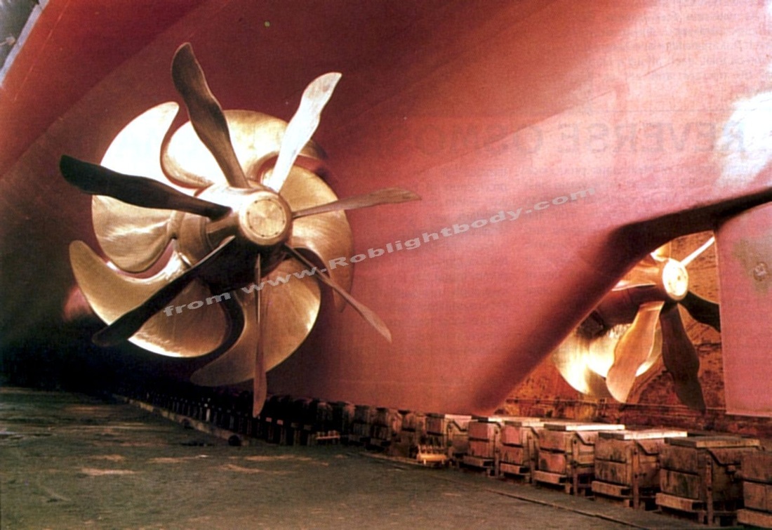
QE2's new propellers and Grim Wheels
Note: The Grim Wheels were short lived. They lost blades during extreme full-astern testing (over 19 knots!) following the refit and were removed, never to be replaced.
QE2's new propellers were completely different to her old ones. Her old propellers had been fixed pitch, just like her predecessors. This meant that in order to change speed, she had to actually slow her turbines. With the new controllable pitch (CP) propellers, the shafts run at a steady speed of either 72 or 144 rpm, and speed is determined by the pitch of the propeller blades. The new propellers are 5 bladed with a 5.8 meter diameter. Each propeller is designed to absorb up to 65,000 shp.
QE2 is the first passenger ship to use Grim Wheels (so called because they were invented by Dr Ing Otto Grim) in an attempt to make the new QE2 even more efficient. These wheels spin freely in the wake of the main propellers. The innermost parts of each of the 7 blades pick up speed from the propeller, while the outermost parts act as propellers themselves, adding some forward motion to the ship for "free", capturing energy which would otherwise be wasted. The Grim Wheels are 6.7 meters in diameter.
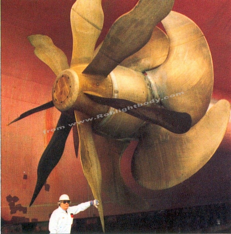
A QE2 propeller with a man underneath to show scale
|
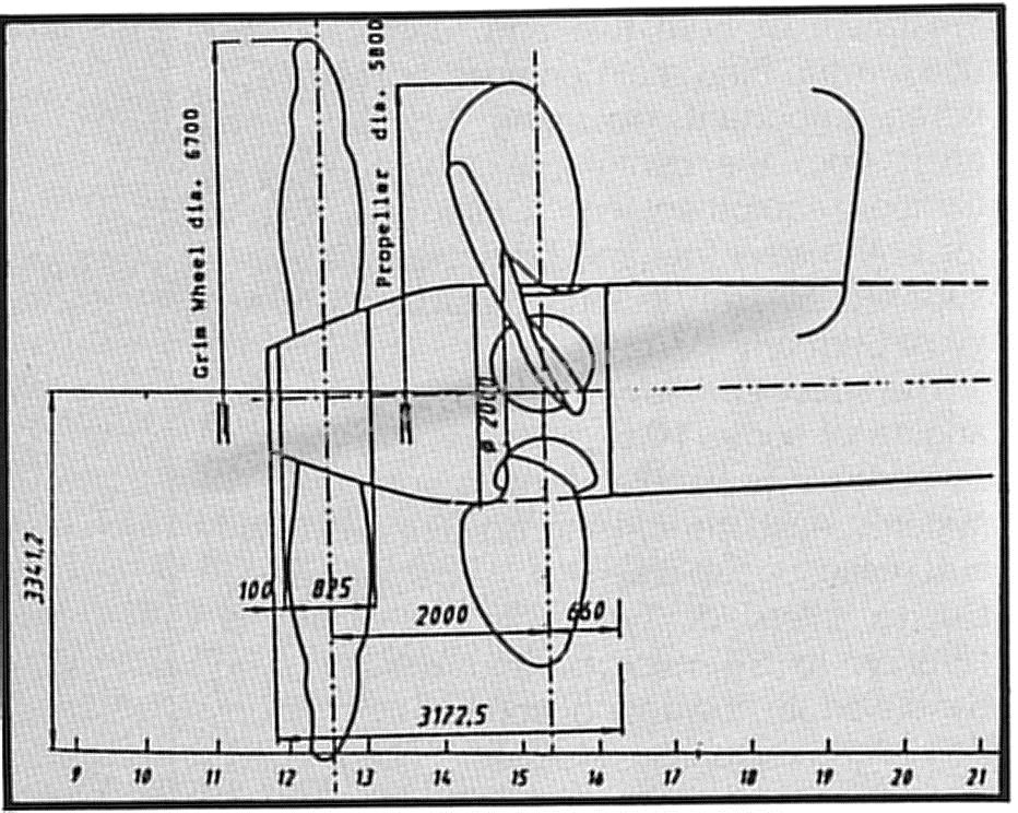
Sketch of the propeller and Grim Wheel arrangement on the QE2
|
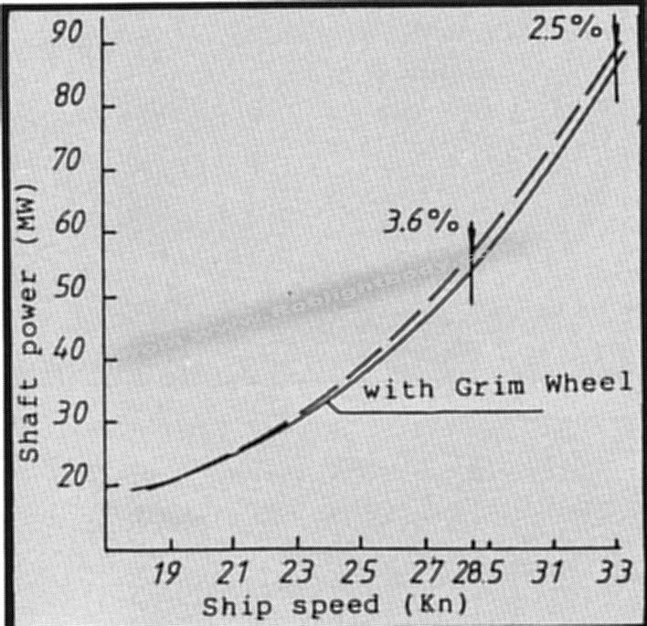
Graph showing power absorption by the propellers at constant rev/min and corresponding ship speeds
|
All new electronic controls
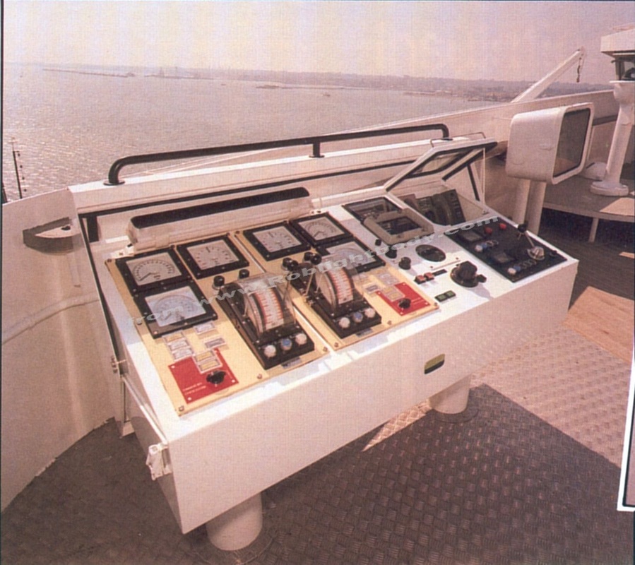
Bridge wing propeller and thruster controls
|
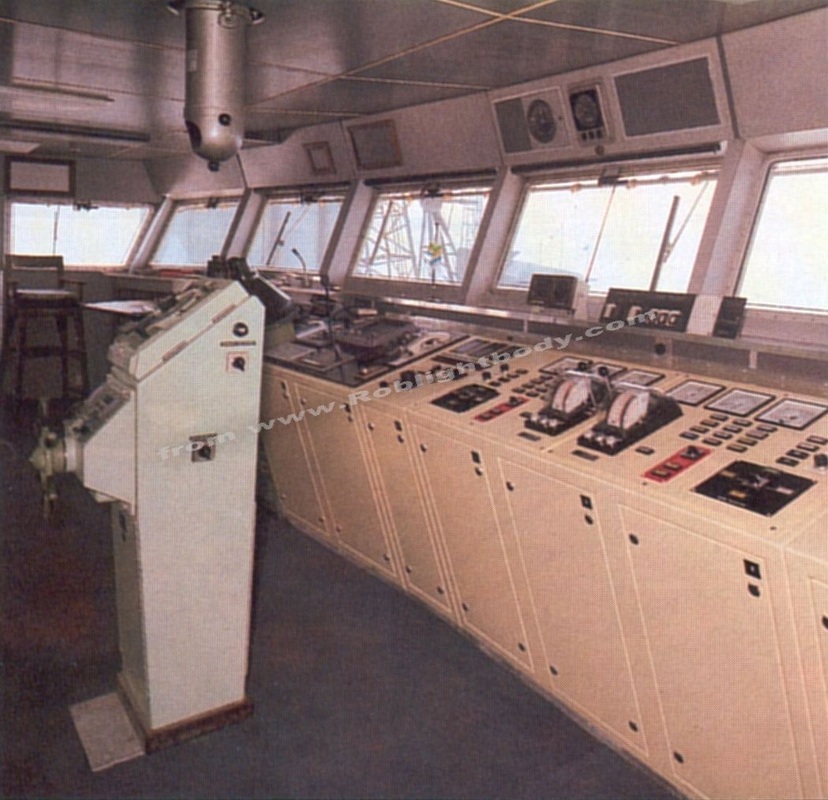
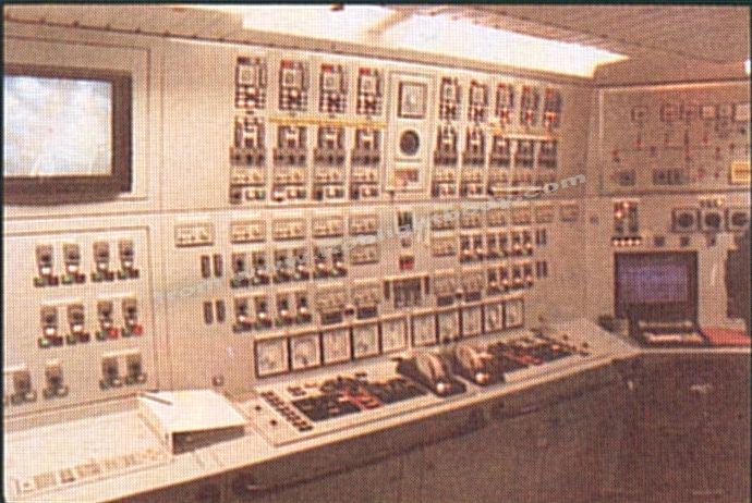
Manoeuvring panel in the wheelhouse
|
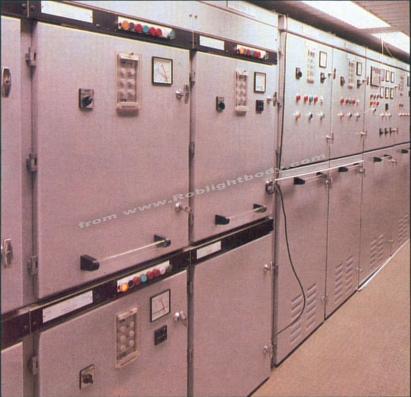
Section of the main switchboard
|
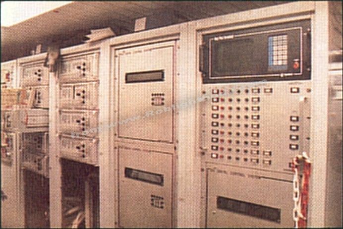
Machinery controls and alarms
|

Cooling system alarm panel
|
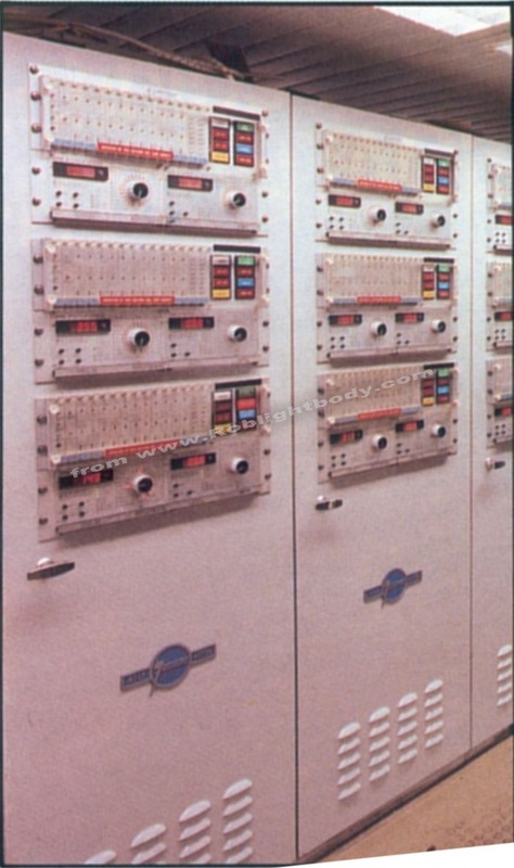
Engine power management panels
|
Machinery alarm panels
|
Refurbishment Work
- Eight more penthouse suites were added to the existing suites on the top deck of the vessel
- The Double Down public area which extend over two decks was entirely rearranged and supplemented by an attractive new shopping centre operated by Allders, As well as the shops, a new bar and leisure room for adults and teenagers were created.
- The shops are arranged in an open, almost galleria type, presentation of small boutiques around the spectacular Double-up Room balcony. These are linked by a meandering walkway that allowed several windows to be re-opened to allow in natural light, before leading into the more comprehensive shopping area aft.
- Renewal work was completed in Tables of the World restaurant, the ships kitchens and laundries were extensively refitted and all other dining rooms and public spaces were given a new appearance. A large number of passenger cabins were either upgraded or refurbished while crew mess rooms and leisure facilities were also considerably improved.
- A new International Food Bazaar, open to all passengers, for evening culinary/beverage sampling.
- Ship to shore communications were also considerably improved to offer the facility of a new telephone system with direct dialling from each cabin to shore numbers via Satcom. Satellite TV also now available.
- Much new furniture was added as well as new English carpets.
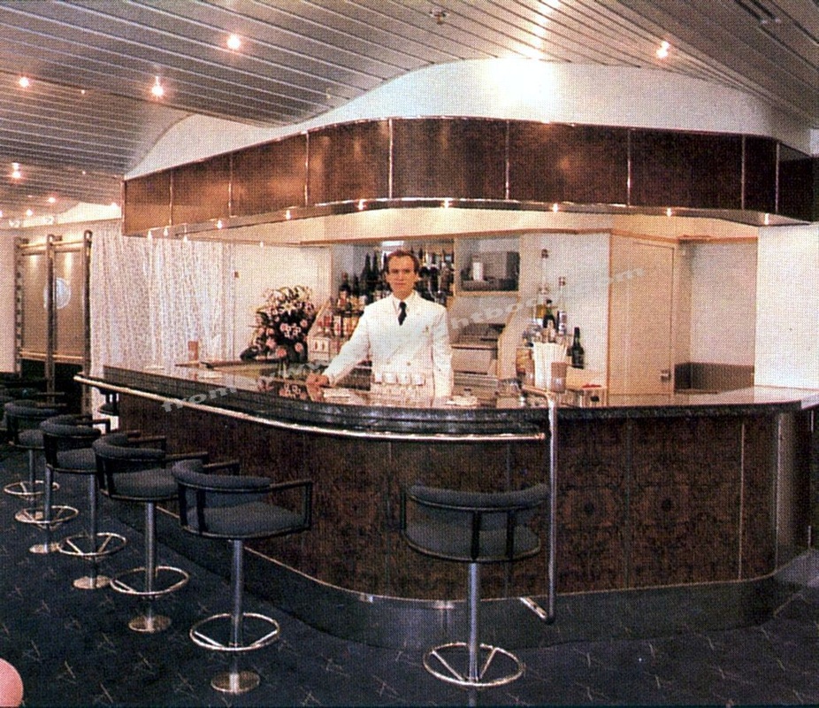
The yacht club bar
|

Penthouse
|

A new First class suite
|
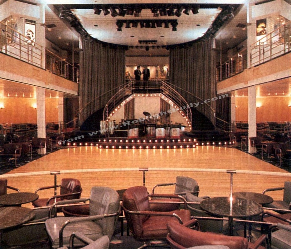
The Grand Ballroom which had, prior to this refit, been known as the Double-Up and Douple-Down room
|
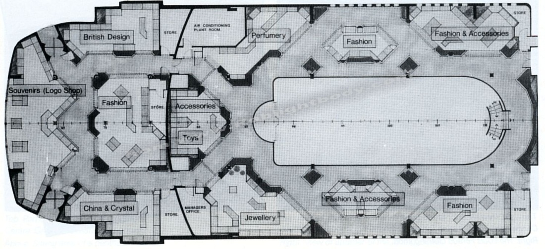
Original artists plan for the new shops.
|
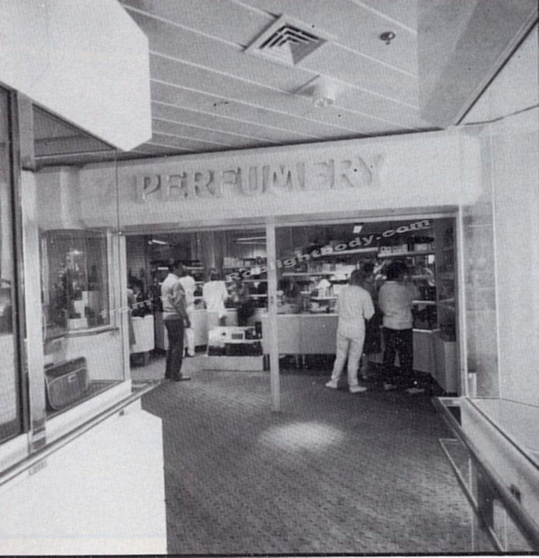
The new perfumery
|
Painting QE2
- All paint was supplied by International Paints
- Underwater hull recoated with Intersmooth HISOL, the top of the range self polishing copolymer antifouling paint.
- Specially formulated "Cunard orange" paint was created for her boottop area.
- Specially formulated "QE2 Federal Grey" Interlac alkyd gloss finish for the lower topsides.
- White topsides and superstructure applied with interfine antistain.
- Engine room painted in flame retardant paint.

The underwater hull after coating with international paint's intersmooth HISOL. You can also see the new propellors and Grim Wheels.
Firefighting Refurbishment
Completely new machinery spaces meant a new fire fighting system here while in the accommodation, new systems added and upgrading the old have taken place. Fixed & Portable CO2 bottles, halon smothering systems, 1200 sprinkler heads were replaced. The number of sprinkler heads in the ship has increased to 8,500.
Completely new machinery spaces meant a new fire fighting system here while in the accommodation, new systems added and upgrading the old have taken place. Fixed & Portable CO2 bottles, halon smothering systems, 1200 sprinkler heads were replaced. The number of sprinkler heads in the ship has increased to 8,500.
QE2 Refit Supplier Adverts
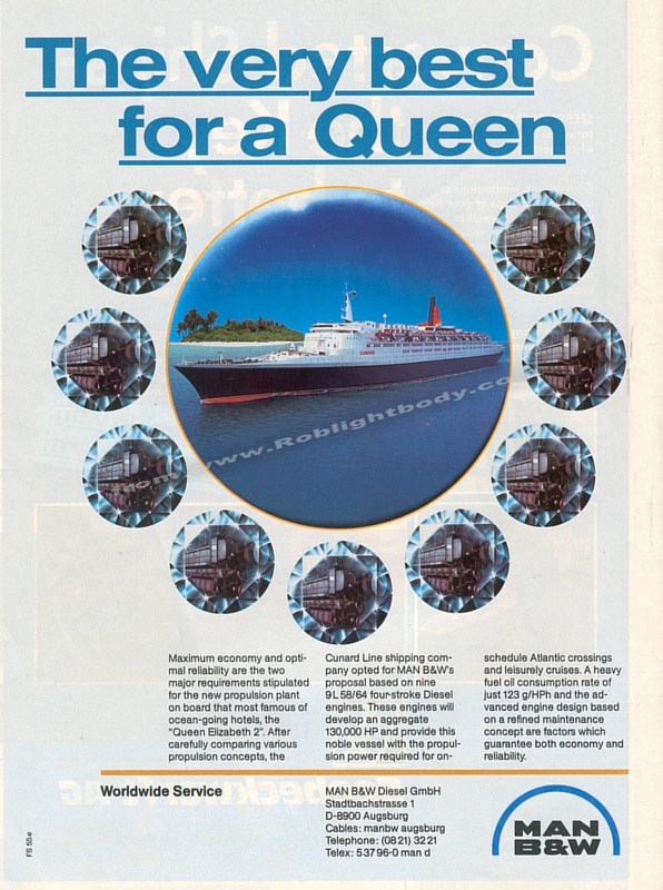
M.A.N. B&W - Suppliers of the main engines
|

Conti Schwingmetall -Stopping the vibrations from 130,000 shp!
|
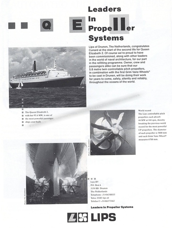
LIPS - suppliers of the new propellers
|
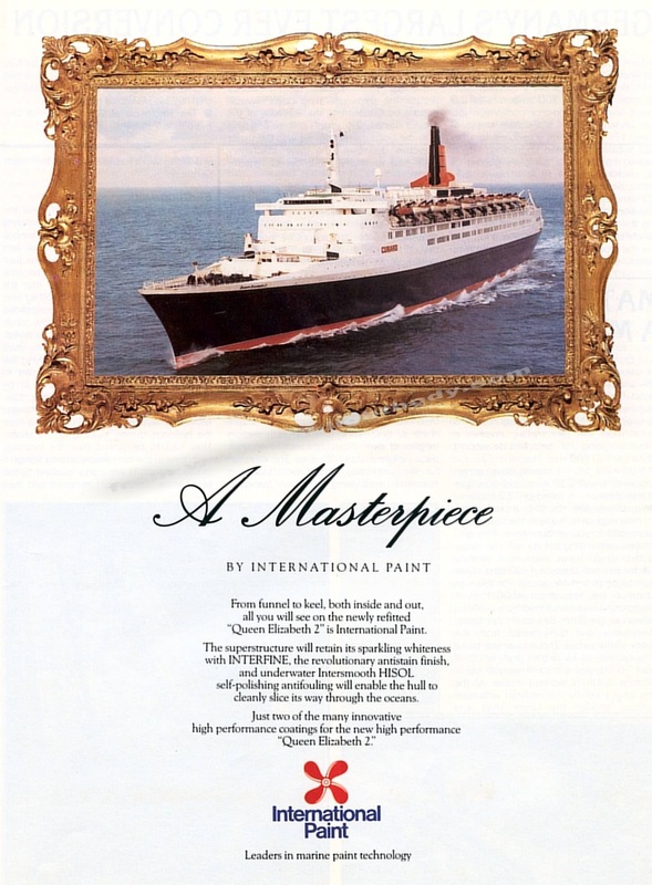
International Paints
|

Lloyd Werft "Made in Germany"
|
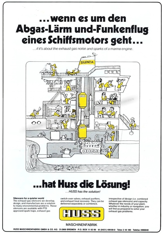
Huss Silencers - so you can hear the orchestra
|
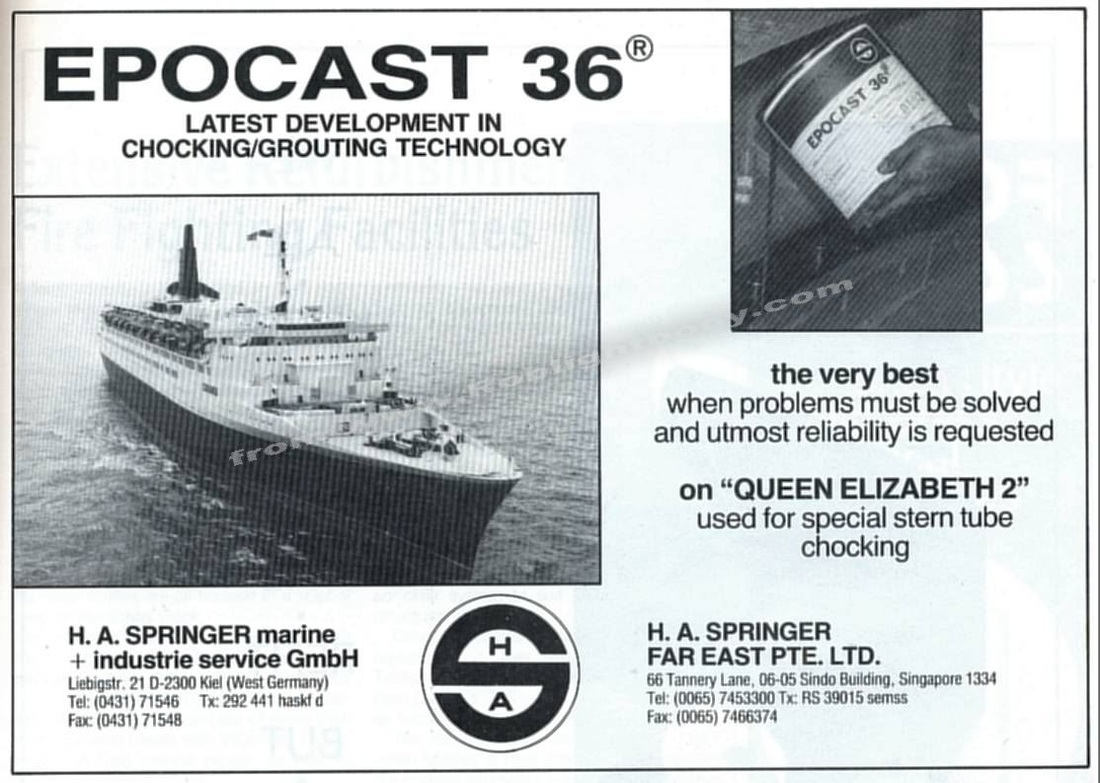
Epocast
|

Lastra
|
YouTube Videos
|
|
|
|
Your Comments